

What Is a Universal Board TV and How Does It Work?
A television can look finished from the outside while one small circuit board determines whether it starts, displays a picture, or responds to a remote. A Universal Board Tv is a replacement control board designed to operate with multiple television models, rather than one exact model alone. It typically processes signals from HDMI and other inputs, runs the television’s software, and sends image and sound instructions to the relevant components. Some kits also combine functions that were separate on the original set. The name sounds broader than the reality. Compatibility still depends on the screen panel, connectors, firmware, and power requirements.
The repair context matters. The Global E-waste Monitor 2024, produced by UNITAR and the International Telecommunication Union, estimates that the world generated 62 million tonnes of electronic waste in 2022; only 22.3% was documented as formally collected and recycled. That figure covers electronics broadly, not televisions alone, but it underlines why repair options deserve careful attention. A universal board may help restore a working set, yet it is not automatically a plug-and-play fix. A mismatched panel setting can produce a blank screen, wrong colors, or no image at all. Not quite universal. This guide explains what the board does, how signals move through it, and which compatibility details matter before choosing one. It also considers the limits: model labels can be incomplete, and a board swap may not solve faults elsewhere in the television.
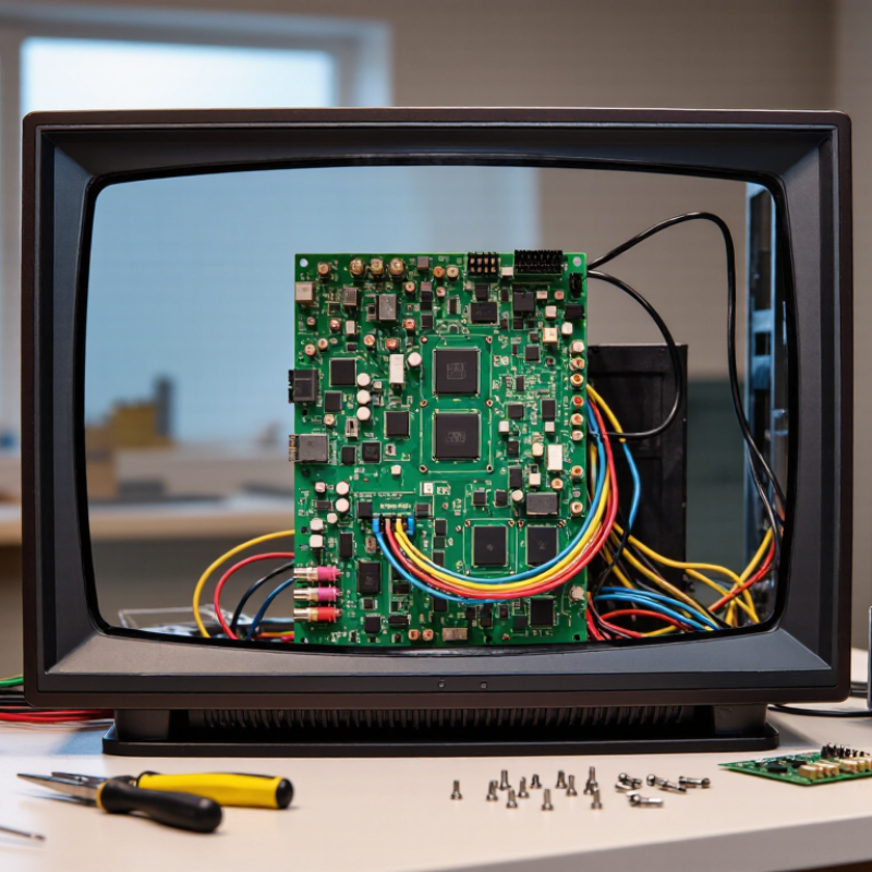
What a Universal Board TV Is
A universal board TV is a television fitted with a replacement control board designed to work across multiple models, rather than one specific set. It is not a universal standard. The board typically processes video and audio, manages inputs such as HDMI, and sends a picture signal to the display panel. Some versions also include a broadcast tuner. The power supply may remain a separate board.
Compatibility depends on details. Check the panel’s resolution, connector type, signal format, and operating voltage before fitting a board. A connector that looks right can still carry a different signal. Firmware and remote-control support matter, too. In practice, a repair technician checks the panel label and board documentation, then tests the set before closing the case. Small mismatches can cause a blank screen or distorted picture. It is easy to overlook one.
The Global E-waste Monitor 2024 reports that the world generated 62 million tonnes of electronic waste in 2022; only 22.3% was formally collected and recycled. That figure does not prove every board replacement prevents waste, but it gives repairability real context. A compatible board may keep a television useful longer. Still, compatibility should be verified—not guessed.

What Is a Universal Board TV and How Does It Work?
A universal TV board processes signals from sources such as HDMI, then converts them into signals a compatible display panel can use. This chart compares the approximate number of pixels per frame at three common resolutions. The board and panel must support the same resolution and timing for the picture to display correctly.
The Main Components of a Universal TV Board
A universal TV board is a replacement control board designed to support multiple television models, but “universal” does not mean it fits every screen. Its main components usually include a power supply, a main control section, and connectors for the display and other parts. Some designs combine these functions on one board; others use separate modules. Small, but important.
The power section converts household electricity into lower voltages used by the television. It may also supply the LED backlight, either directly or through a dedicated driver. The main section processes incoming signals, runs the operating software, and sends picture data toward the panel. A tuner or audio circuitry may also be included. On some models, timing control is built into the panel or board, so layouts vary.
Look closely at the ribbon sockets, cable positions, and printed voltage labels. They are not decorative details. The panel’s resolution, connector pinout, and firmware must match the board’s configuration, or the screen may remain blank or show distorted colors. That matters. “Universal” can sound broader than it is, and compatibility lists may not explain every revision. Power sections can retain charge after unplugging, so board inspection or replacement should be handled by a qualified technician.
How the Board Processes Signals and Displays Images
A universal TV board receives signals from connected devices, such as a streaming box, antenna, or game console. At an HDMI input, it identifies the incoming format and decodes the audio and video data. The video processor then scales the picture to suit the screen’s resolution. A small image may be enlarged; a higher-resolution image may be reduced. Neither process can restore detail that was never present.
Next, the board sends carefully timed image data toward the display panel. Depending on the TV design, a separate timing controller may handle this step, or some functions may be built into the board. The panel uses the data to set each pixel’s color and brightness. Meanwhile, a backlight circuit illuminates the screen in many LCD televisions. Tiny timing errors can cause flickering, lines, or a blank picture. The symptoms can overlap, so diagnosis is not always obvious.
The board also manages input selection, menus, and remote-control commands. It may route sound to speakers or an audio output, while separate circuits control volume and backlighting. “Universal” does not mean every board fits every television. Connectors, panel timing, firmware, and screen specifications must match. A mismatch can produce sound without a usable image, or no image at all. Checking the panel label and service information is a practical starting point, though it does not guarantee compatibility. The signal path is simpler on a diagram than inside a real set.
How to Match and Install a Universal Board
A universal TV board is a replacement control board, but “universal” does not mean it fits every television. Match the board to the exact screen panel, not just the TV’s size or case. Check the panel label for its model number, resolution, and interface type, such as LVDS or eDP. Compare connector shapes, pin counts, and required voltages with the board specifications. Small differences matter. A similar-looking connector can still be incompatible.
Before installation, unplug the TV and let it sit. Internal power components may retain dangerous voltage, so avoid touching the power-supply section. If you are not trained to work inside electronics, ask a qualified technician to fit the board. Take clear photos of the original connections, then compare each cable and mounting point with the replacement board’s instructions. Never force a connector. Confirm that the board’s firmware supports the panel and that the remote and control buttons are compatible. I have found that checking these details twice can prevent a frustrating, avoidable mismatch.
Tips: Use an antistatic work surface, keep screws organized, and check every cable before powering on. If the display stays blank, disconnect power and recheck compatibility rather than swapping wires at random.
| Topic | What to Check | Typical Details | Matching or Installation Guidance |
|---|---|---|---|
| What a universal board does | Converts incoming video and control signals for a compatible LCD panel. | A typical kit may include a main controller board, button or remote receiver, and cables. | It is not universally compatible with every TV panel; the panel’s electrical and signal specifications must match. |
| Panel model | Find the complete model number on the label attached to the LCD panel. | The panel label may also list resolution, interface, and supply information. | Use the exact panel model to check the board’s compatibility list and obtain the correct firmware configuration. |
| Resolution and timing | Check the panel’s native resolution and supported timing. | Common examples include 1366 × 768 and 1920 × 1080 pixels. | The board firmware must support the panel’s native resolution and timing; a similar screen size alone is not enough. |
| Panel interface | Identify the signal interface and connector pin count. | LVDS panels commonly use 30-pin or 40-pin connectors. Some newer panels use eDP instead. | Connector shape and pin count do not guarantee compatibility. Confirm the interface, pinout, and signal configuration before connecting. |
| Panel voltage | Verify the panel’s required supply voltage from its documentation or label. | Panel supply requirements vary; 3.3 V, 5 V, and 12 V are examples found in display systems. | Set or select the correct output before powering the panel. The wrong voltage can damage it. |
| Backlight type | Determine whether the panel uses LED or CCFL backlighting. | LED panels need a compatible LED driver; CCFL panels require an appropriate inverter. | Match the driver and cable to the backlight type and its electrical requirements. Do not connect incompatible backlight hardware. |
| Input and control connections | Check the board’s available video inputs, button board, and remote receiver. | Available inputs vary by board; HDMI and other interfaces may be provided. | Confirm that the board supports the sources and controls needed for the intended setup. |
| Before installation | Prepare a clean, dry, static-aware workspace and inspect all connectors. | LCD panels and ribbon cables are fragile; power supplies may contain hazardous voltages. | Unplug the equipment and allow it to discharge. Avoid working on a powered set; seek qualified help if unsure. |
| Installation sequence | Fit the board, connect the panel cable and backlight, then attach the controls and power supply. | Connector orientation and cable routing depend on the panel and board. | Follow the board and panel documentation. Check alignment and polarity; never force a ribbon connector. |
| First power-on and troubleshooting | Test with a supported input and inspect the image and backlight. | A blank, distorted, or incorrectly colored image can indicate a wrong firmware setting, interface mode, cable connection, or voltage. | Disconnect power before changing connections. Recheck the panel model, firmware, pinout, and voltage before testing again. |
Common Uses and Limitations of Universal TV Boards
A universal TV board is a replacement control board designed to work with a range of television panels. It processes video signals, manages inputs, and sends image data to the screen. In a repair, a technician may use one when the original board is unavailable or uneconomical to replace. The board can also help bring an older panel back into service. That is the appeal.
“Universal” does not mean every board fits every screen. The panel’s resolution, timing, connector type, and voltage must match the board’s settings. For example, a loose LVDS or eDP connection can leave the screen blank or produce distorted colors. Firmware and menu controls may also differ from the television’s original setup. In practice, the label can be misleading. Checking the panel’s model code and technical specifications matters more than judging by connector shape alone.
These boards suit repair shops and experienced hobbyists who can identify compatible components and configure the display. Installation involves more than plugging in a few cables; incorrect wiring can damage the panel. Power supplies can retain hazardous charge, even after unplugging, so inexperienced users should seek qualified help. A universal board may restore basic viewing, but features such as built-in speakers, remote functions, or smart-TV menus may not work as expected. Sometimes the simplest repair is not the best one.


